Make More 432MHz EME Contacts
by
Polarization Rotation
This is a version of my article in DUBUS 3/1996.
Page 1 of 3

1996 - but see
what happened in 2001
| Because the polarization can always be accurately optimized, my small antenna with 12 short yagis will often perform as well as a much larger fixed horizontal array. With only 700W, I have worked many new stations that would have been impossible without polarization rotation. In contests, this array gets to places that fixed polarization cannot reach! |
|
CONTENTS
1. Polarization Problems |
Polarization ProblemsFor amateur EME (Earth-Moon-Earth = moonbounce) communication on the 50MHz, 144MHz and 432MHz bands, we use horizontal linear polarization, the same as we use for other kinds of VHF/UHF DX. A big problem with VHF/UHF EME is that the transmitted polarization is usually rotated before it reaches the receiving station, so there can be very large losses in signal strength. Remember also that EME signals are always close to the noise, with rapid fading, so a 3dB signal loss can make the difference between a QSO or no-QSO! Even a 1dB loss can be serious.
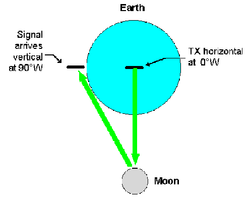
To keep the signal losses below 1dB, the polarization error must be less than about ±20-30°. The good news is that the signal loss within the ±10-20° region is very small. Geometrical (spatial) rotationIf the transmitting and receiving stations are on two different continents, there will almost always be polarization rotation between them. The diagram shows why this happens.
When the moon is exactly south (azimuth 180°) in Europe, a signal transmitted towards the moon with horizontal polarization will arrive in the mid-western USA with its polarization close to vertical. The geometrical polarization angle (sometimes called 'spatial polarization') between the same two stations will change with the position of the moon, and computer programs can predict this very well. When you are listening for your own echoes from the Moon, geometrical rotation is exactly zero at all times. Geometrical rotation between stations in western Europe is never more than about 10°, which is nothing to worry about (maximum polarization loss 0.1 to 0.2dB). But long east-west paths are a different story, because geometrical rotation changes greatly through the moon window time. For example, geometrical rotation between Europe and the W0 call-area is quite small at moonrise in the USA; the rotation increases to almost 90° as the moon is at its highest, and then decreases again towards moonset in Europe. For quite long periods, the geometrical rotation can be close to +45° or -45°; this can have some very bad consequences, as we shall see... because geometrical rotation is not the only problem! Faraday rotationFaraday rotation occurs when a linearly polarized signal passes through the ionosphere. When the electromagnetic wave interacts with the charged particles and the Earth's magnetic field, its plane of polarization is rotated. When the rotated signal has been reflected back from the moon and re-enters the ionosphere, it will be rotated some more in the same direction - Faraday rotation does not 'un-wind' or cancel out! This means that even your own Moon echoes can return rotated by 90°, so you don't hear them. In these conditions, EME QSOs between stations anywhere in Europe with fixed horizontal polarization will be very difficult. Faraday rotation can not be predicted in advance: you have to accept whatever it is at the moment! Although the signal only seems to arrive at a polarization angle between +90° and -90°, the wave may in fact have undergone many complete rotations. Faraday rotation is proportional to the electron density, integrated along the path through the ionosphere. When the path through the ionosphere is longer, at your local moonrise and moonset, there will be more rotation. Also there is more ionization in daytime: Faraday rotation is about 10 times more severe in daytime than at night, and it is likely to be changing the most quickly around sunrise or sunset at either end of the EME path. Faraday rotation is proportional to 1/(frequency)-squared, so that when the ionosphere does change, the polarization angle changes 9 times more rapidly at 144MHz than it does at 432MHz. This can have many unfavourable consequences. At 144MHz in unstable conditions, Faraday rotation can change rapidly enough that you can lose a station before the QSO is complete; but when the ionosphere is stable, the polarization at 432MHz can remain 'stuck' at a bad angle for the whole day. In disturbed ionospheric conditions, EME signals can return to earth with their polarization spread over a wide range of angles. In extreme cases the signal strength is the same at all polarization angles, which means an extra signal loss of 3dB. Unfortunately this polarization spreading is often accompanied by high ionospheric absorption and all signals are very much weaker than usual. Geometrical rotation + Faraday rotation = Big Trouble!N1BUG has clearly identified that the real problem is not either geometrical rotation or Faraday rotation on its own - the problem is the combination of the two effects [1]. There will always be a combination of geometrical rotation and Faraday rotation on an EME path. When you are working a long way east or west, to another continent, the Faraday rotation will probably not be the same at each end of the path, because of the time difference. As a result, the situation can be very complicated. If you have only fixed horizontal polarization, the polarization will usually not be correct to give the best signals in both directions between two stations. Sometimes you can hear your own echoes and work your own continent; sometimes you can work W or JA stations when you can't hear your own echoes; and sometimes you just can't near or work anybody at all! It can be very confusing. Worst of all are the cases where geometrical and Faraday rotations combine to give one-way propagation. This is most likely to occur when the geometrical rotation on a long east-west path is about ±45°. N1BUG has confirmed this by analysis of many EME logs [1]; he found that two horizontally-polarized stations are very unlikely to work each other when the geometrical rotation between them is close to ±45°. Unfortunately this situation happens two times in every Europe-USA moon window. If you have fixed horizontal polarization, one-way propagation is very real and very frustrating. Sometimes European stations can hear W stations calling CQ, but they never come back to our calls... they just keep on calling CQ. We can hear them because their signals arrive horizontally polarized in Europe; but our signals are arriving vertically polarized in the USA, so they cannot hear us. And sometimes it works the opposite way: we in Europe call CQ, but we don't hear the W stations calling us because their signals are arriving vertically polarized over here. After several hours of one-way propagation, it becomes easy to imagine that the other guys have deaf receivers; don't want to work us; are not really serious about EME... Fixed horizontal polarization can be very bad for international relations! What Can We Do?It's very simple - escape from fixed horizontal polarization!
|
||||||||||||||||||||||||||||||
|
CONTENTS
1. Polarization Problems
|
How To Rotate PolarizationYou have two basic choices: either you can rotate the polarization mechanically, by physically moving the antenna; or you can rotate the polarization electronically. The optimum method depends on your type of antenna, and also on the frequency. For a parabolic dish, mechanical rotation is easy because you only have to rotate the small feed antenna. This is a very simple way to rotate the polarization, but most people who have a dish for 432MHz are also working on 1296MHz with a dual-band feed. This feed system has switchable horizontal and vertical dipoles for 432MHz, so there can be a polarization error of up to 45° (3dB loss). Switchable horizontal/vertical polarization is not ideal, but it is much better than horizontal-only. On 144MHz, almost all stations use yagis. A few 144MHz stations have had success with polarization-rotatable yagi arrays, but that means rotating the complete array, and mechanical problems have usually restricted this approach to small arrays with low gain. Crossed yagi arrays for 144MHz can be very successful, as described by SM5BSZ [2] and SM2CEW [3]. F/G8MBI has had great success with a single, long crossed yagi. The breakthrough has been to use computer modelling to minimize the effects of the stacking frame on the gain and pattern of the array. SM2CEW and F/G8MBI both use crossed yagis in the '+' configuration with simple horizontal/vertical switching. SM5BSZ mounts his yagis in the 'X' configuration and uses phasing lines to switch the polarization in 45° steps, so that the error is never more than 0.7dB [2, 4] and it is also possible to vary polarization in smaller steps or continuously. Electronic systems for polarization rotation require two low-noise preamps with carefully matched gain and phase, and a lot of coaxial relays. SM5BSZ's EME Technical Notebook tells you all about it! Crossed yagi arrays for 432MHz are more difficult to feed with accurate phasing and low losses than at 144MHz. F/G8MBI and SV1BTR have both made a successful crossed 4-yagi EME array for 432MHz. Continuous polarization rotation with a crossed yagi array at 432MHz is still in the future, but watch this page! Continuous polarization rotation with yagis at 432MHz still involves mechanically rotating the whole array. This is not difficult - it's much easier than at 144MHz - and the next page will show you how to do it.
|
||||||||||||||||||||||||||||||
|
CONTENTS
1. Polarization Problems
|
Back to: GM3SEK's Amateur Radio Technical Notebook |
Updated 18 April 2010
Page © 1997-2001 IFWtech.